

Electrical Resistors: The Control Valves of Circuits
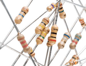
In the world of electronics, we often hear about voltage, current, and components like batteries and LEDs. But one of the most fundamental and essential components is the resistor. It’s the unsung hero that keeps circuits from self-destructing and allows them to function as designed. This article will explore the purpose of resistors, how they affect current, and what happens when we connect them in series and parallel.
What is a Resistor and What is its Purpose?
A resistor is a passive two-terminal electrical component that implements electrical resistance as a circuit element. In simpler terms, it’s a component designed to oppose the flow of electric current.
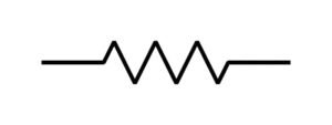

Its primary purposes in a circuit are:
To Limit Current: This is the most common use. Many components, like LEDs, are very sensitive to high currents and will burn out almost instantly if not protected. A resistor placed in series with an LED ensures that only a safe, small amount of current flows through it.

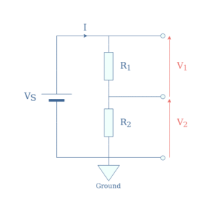
To Divide Voltage: When resistors are connected in a specific way (a “voltage divider”), they can create a lower voltage from a higher one. This is useful for providing a specific reference voltage to sensitive parts of a circuit.
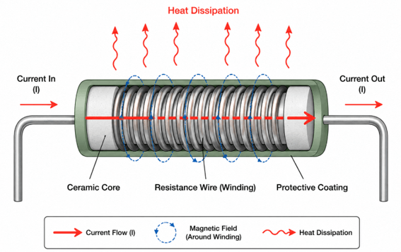
To Generate Heat: While often seen as an unwanted byproduct, this is the principle behind electric heaters, toasters, and incandescent light bulbs. They use resistive materials that get hot when current flows through them.
To “Pull Up” or “Pull Down” Signals: In digital circuits, resistors are used to ensure a wire has a stable “high” (e.g., 5V) or “low” (0V) voltage state when no other component is actively driving it.

The unit of resistance is the Ohm (Ω), named after Georg Simon Ohm. A higher resistance value means the component opposes current flow more strongly.
The Effect of a Resistor on Current: Ohm’s Law

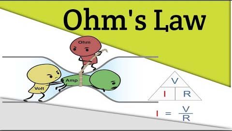
The relationship between voltage (V), current (I), and resistance (R) is elegantly described by Ohm’s Law, one of the most important formulas in electronics:
I = V / R
Where:
- V is the voltage (potential difference) across the resistor, measured in Volts.
- I is the current flowing through the resistor, measured in Amperes (Amps).
- R is the resistance, measured in Ohms.
From this law, we can see the direct effect of a resistor on current:
This means that for a given voltage, the current is inversely proportional to the resistance.
- If you increase the resistance (R), the current (I) decreases.
- If you decrease the resistance (R), the current (I) increases.
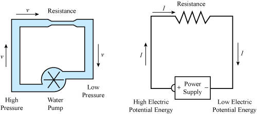
Think of it like a water pipe. Voltage is the water pressure, current is the flow rate, and a resistor is a narrow section of pipe. A narrower pipe (higher resistance) allows less water (current) to flow for the same pressure.
Methods of Connecting Resistors
Resistors can be connected in two primary ways: in series or in parallel. The way they are connected dramatically changes the total resistance of the circuit.

Resistors in Series
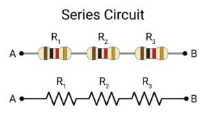
When resistors are connected in a “daisy chain” one after another, they are in series. The current has only one path to follow, so it must flow through each resistor sequentially.
- Method: Connect the end of one resistor to the beginning of the next.
- Result on Current: The current is the same through every resistor in the series chain.
- Result on Voltage: The total voltage is divided among the resistors. The sum of the voltage drops across each resistor equals the total voltage of the source.
- Result on Total Resistance: The total resistance is the sum of the individual resistances.
Formula:
R_total = R₁ + R₂ + R₃ + …
Example: If you have a 100Ω resistor and a 200Ω resistor in series, the total resistance is 100Ω + 200Ω = 300Ω. This increased total resistance will reduce the total current flowing from the source.
Resistors in Parallel
When resistors are connected side-by-side, with their ends connected to the same two points, they are in parallel. The current has multiple paths it can take.
- Method: Connect one end of all resistors together and the other end of all resistors together.
- Result on Voltage: The voltage is the same across every resistor in the parallel group.
- Result on Current: The total current from the source is split among the parallel branches. The sum of the currents in each branch equals the total current.
- Result on Total Resistance: The total resistance is less than the smallest individual resistance. This is because providing more paths for the current to flow makes it easier for it to move.
Formula:
1 / R_total = 1 / R₁ + 1 / R₂ + 1 / R₃ + …
For two resistors in parallel, this can be simplified to:
R_total = (R₁ × R₂) / (R₁ + R₂)
Example: If you have a 100Ω resistor and a 200Ω resistor in parallel, the total resistance is (100 × 200) / (100 + 200) = 20000 / 300 = 66.7Ω. Notice how the total resistance (66.7Ω) is now lower than both individual resistors. This lower total resistance will allow more total current to flow from the source.

Conclusion
Resistors are simple but incredibly versatile components that are fundamental to controlling and managing electricity in circuits. By understanding their purpose, the principles of Ohm’s Law, and how they behave in series and parallel configurations, you have taken a major step in understanding electronics. They are the control valves that ensure the delicate balance of voltage and current is maintained, allowing complex electronic devices to function reliably.

Leave a Reply