
Achieving HYSTERESIS, description and discussion. Continued.

Before we study how to create hysteresis, let’s make sure we are on the same page about three basic concepts
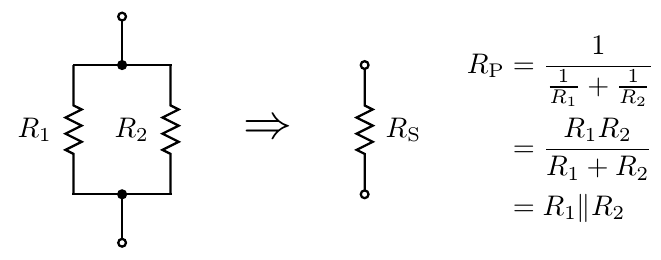
1. Connecting resistors in parallel:
If we connect two resistors in parallel, the resulting resistance will be calculated using this formula:
R = (R1*R2)/(R1+R2)
2. A special case of parallel connection:
If two resistors (A, and B) on the same board have the same voltage (V1) at (Apin1), and (Bpin1), and the same voltage (V2) at (Apin2), and (Bpin2), then they are connected in parallel even if they are not physically soldered together.
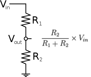
3. Voltage divider:
A voltage divider (also known as potential divider) is a simple circuit that produces an output voltage (Vout) which is a fraction of its input/supply voltage (Vin or Vs). In short, voltage is divided according to the ratio of the resistors. (Vout) can be calculated using the formula: Vout = (Vin*R2)/(R1+R2)
How do we create hysteresis?
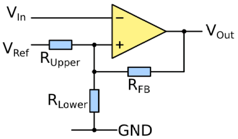
Now we can predict how to create hysteresis using a comparator IC. This is done with positive feedback. We add a feedback resistor, “RFB“, that feeds a small part of the comparator’s output back to its non-inverting input (IN+). Okay, this is easy to say. But how can adding one feedback resistor create a second threshold? What is the mechanism? Let’s understand it with an example.
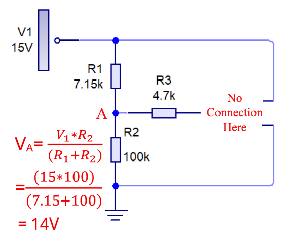
Consider This voltage divider circuit, In this circuit, R3 has no effect on the voltage at point “A” because it is not connected. So, as calculated, VA = 14V.
Now, what happens when we connect R3 to either V1 or Ground?
- When the toggle switch SW1 connects R3 to V1, R3 becomes in parallel with R1. This changes voltage at “A” to 14.59V.
- When SW1 connects R3 to Ground, R3 becomes in parallel with R2 instead of R1. That changes the voltage at “A” to 5.79V. Please, take your time to check calculations.
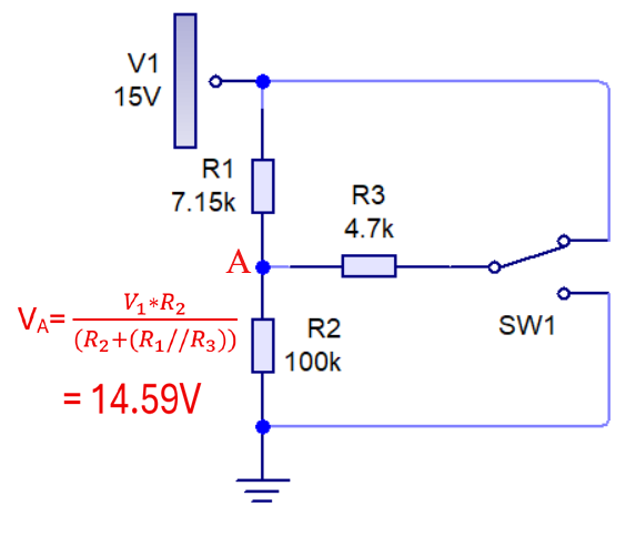
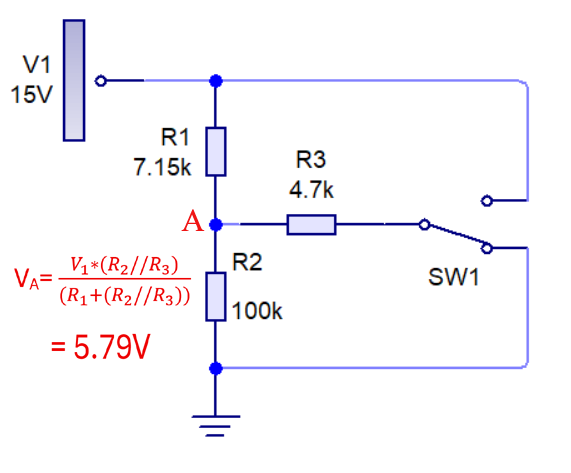
This is exactly what happens inside a hysteresis circuit. The comparator’s output works like the toggle switch, and the voltage at point “A” is connected to the non-inverting input of the comparator “IN+”.
You can see the previous example in action through an interactive demonstration that shows the process of generating two thresholds instead of one—either manually or automatically. Test the process here.
It is worth noting that the technical content and approach presented in this article and blog post are drawn from the *LM393 Hysteresis* handbook, by: Khalid Basyouni. I encourage you to explore the book’s contents, where you will find a wealth of additional practical engineering information. The book explains circuit design in general, with a specific focus on comparator circuits. It details design equations and their practical application, teaching you how to determine the individual impact of each component and resistor on circuit performance and output voltage levels. This way, you can fine tune the performance of the circuit. You will also learn how to verify your design results before physically implementing the circuit. Furthermore, the book offers extensive practical guidance on circuit implementation. You will not regret studying this book and keeping it as a reference for your work, studies, and electronic circuit projects.